
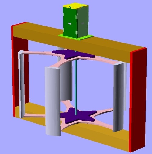
Here’s a longer video showing details of the stepper motor I’m using as an alternator mounted in its housing, the hubs and arms and the coupling to the spindle. I’ve left the third side off the housing to show this. Obviously the whole thing is going to need a coat of paint before I can mount it outside.
I’m really pleased with how much of this turned out. The frame, the spindle and the arms all look just like the CAD design.
The only difficulty I had was with the design of the foils. My initial design was a Darrieus type VAWT with an airfoil at the end of each arm. I cut the foil profile out of the same 6mm MDF I used for the arms and hubs and intended to cover them with corflute. I happened to have a bunch of Green Party electoral billboards left over from last year and wanted to upcycle them for this purpose.
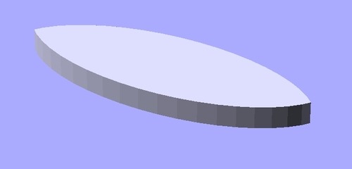
The first design I had was for a simple symmetrical foil made from the intersection of two elipses.
Once I’d cut the parts I realised they were far too big so I decided I had to cut a scaled down version. Out of curiosity I found myself Googling “formula for an aerofoil” and stumbled across a Wikipedia page with an equation to produce a proper NACA aerofoil profile.
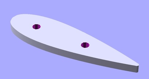
This seemed like a much more pleasing solution so, with an eye to minimising waste, I cut them out of the first foils. You can see how big the first ones were in comparison.

The two holes are 6mm diameter ones which I thought would be useful to help me align the foil profiles between the two arms. I envisaged running 6mm dowels between them to stabilise the foils, which are 0.3m long and would flex if they were just corflute, and to help keep the arms in alignment.
As it turned out 6mm dowel was pretty whippy too and so I bought 8mm dowel thinking I could just drill the holes out. When I got home I had a go at wrapping the corflute around the foil profiles and quickly realised that corflute doesn’t like being bent to smooth, small-radius profiles such as those in the new design. To be frank, I’d probably made the new profile too small! There was no way I was going to get five consistent foils and consistency is pretty important in something that you hope is going to rotate at hundreds of rpm. Imbalances will result in vibration and damage, paticularly in a kludged-up design like this.
So I swallowed my pride, dug around in the garage for a bit and turned up a piece of 55mm PVC drainpipe that I could cut into half-tube sections to turn my elegant Darrieus VAWT design into a clumsy and inefficient Savonius VAWT. Feel free to read up on the differences in the two designs. In brief, the Darrieus type relies on lift from aerofoils, whereas Savonius types utilise drag from buckets to produce torque. The former produces higher tip speeds and faster rotation, which is more efficient for generating power. As a result Darrieus turbines usually capture more energy from the wind than Savonius types, although each have their advantages. The 55mm pipe is probably too small for this and I’d see a lot more power from a bigger section but it was all I had to hand. For this reason the buckets are only zip tied on so I can easily replace them with larger ones in the future.
Anyway, this at least allowed me to finish assembling the pieces and to pop it out on the deck to grab the passing breeze. I’m really happy that the thing turns smoothly on the two 608 bearings as these are meant to be rotational bearings, not thrust bearings. For this reason I left the second set of bolts out of the hubs to minimise weight. They did not seem necessary for structural integrity, thanks to the close fit of the lasercut pieces.
The stepper motor lined up beautifully and, after a little grinding with the Dremel the coupling was a perfect fit. I haven’t checked the voltage coming off the stepper yet. I used the smaller NEMA16 rather than the NEMA23 as the bigger stepper just seemed to require too much torque to turn the shaft. These aren’t really very well suited to this application but this is just a fun project and I’m not aiming to generate any significant power. My main goal here is to get an idea of the potential of this design.
One challenge left, besides the big question of where to mount it, is what to do with the output. The stepper will produce 4-phase AC which will need to be rectified and fed into a battery. I’m contemplating building my own rectifier from Schottky diodes scavenged from old PC power supplies but it is probably quicker, more reliable (i.e. smarter!) to just buy four bridge rectifiers. I’d also like to use an Arduino to log things like the rotation speed- easily derived from the AC frequency- and the voltage and power generated. Although this thing is essentially a great big anemometer it would be interesting to get another proper one to ground truth my measurements. All fun for the future!

